Building Integrated Models in DOME
Assumptions:
- You are familiar with DOME (see the User Guide)
- You have already built two models, shown in Figures 1 and 2:
- Force Model: F (N) = m (kg) * a (m/s^2)
- Work Model: W (J) = f (N) * x (cm)
- You have deployed these models to a DOME server.
The integrated model will connect F, the output of the force model, to f, the input of the work model. With the integrated model a user defines the values of m, a, and x, and the model returns W.
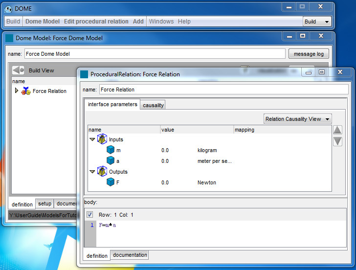
Figure 1
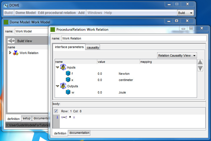
Figure 2
Now you want to integrate the two models so that the force calculated in the first model becomes an input of the second model. The inputs of the integrated model are the mass m, the acceleration a, and the distance x.
This tutorial covers the basics of building and deploying the integration project. The steps are:
- creating a new project
- subscribing to resource models
- creating an integration model
- creating mapping between parameters
- defining project interfaces
- deploying the project
- running the project.
Creating a new project
Start from the DOME window in build mode, Figure 3.

Figure 3
Choose Build > New Integration project, Figure 4.
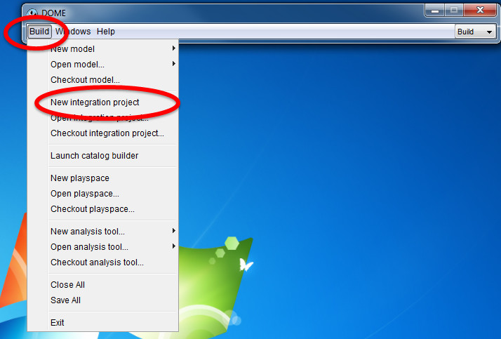
Figure 4
An Integration Project window appears, as shown in Figure 5
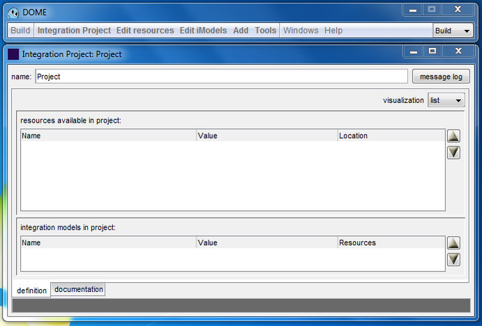
Figure 5
Subscribing to resource models
An integrated model is comprised of individual models and other integrated models, all called "Resources". You need to insert resources available in the project in the related window. To do this, select Add > Resource from the DOME client window, as shown in Figure 6.
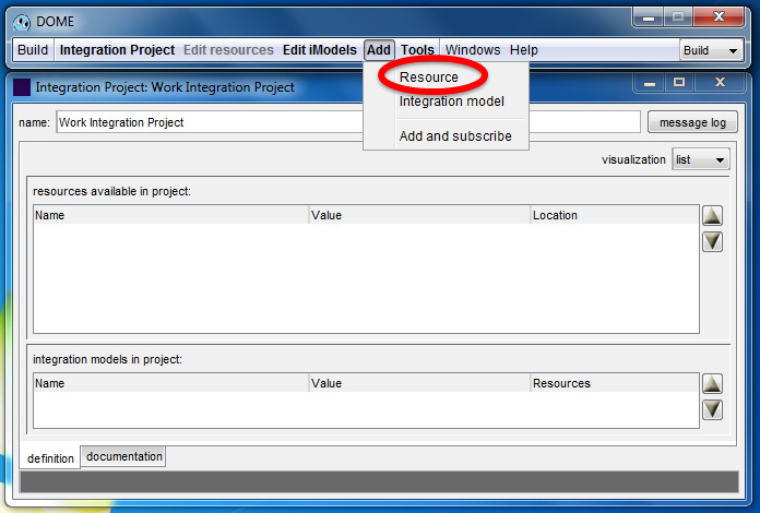
Figure 6
An add resources window appears. If you are not connected with the server, click on login to log into the server and add the needed resources, Figure 7.
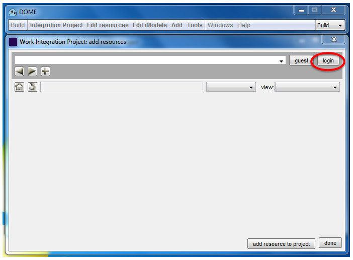
Figure 7
If you logged into the server before the recent login information is stored and showed into a Login to DOME Server window, Figure 8.
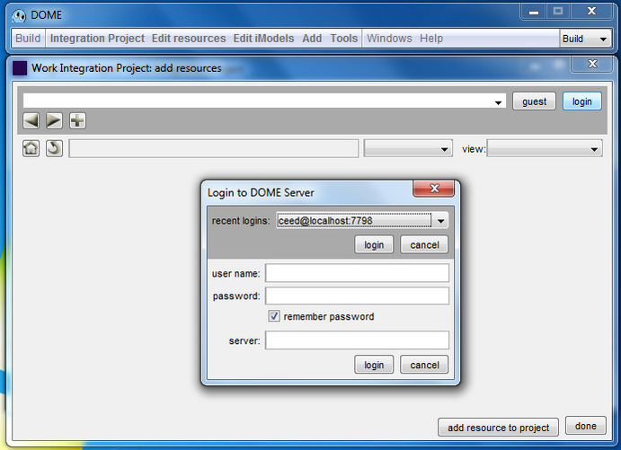
Figure 9
Once connected to the server you can navigate to the location your resources are, Figure 10.
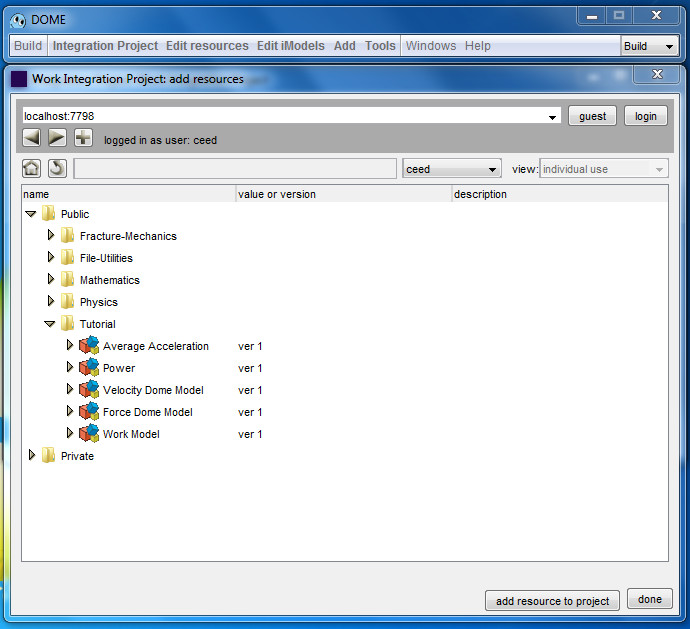
Figure 10
Click on the resources you need for the integrated model and click “add resource to project”, Figure 11.
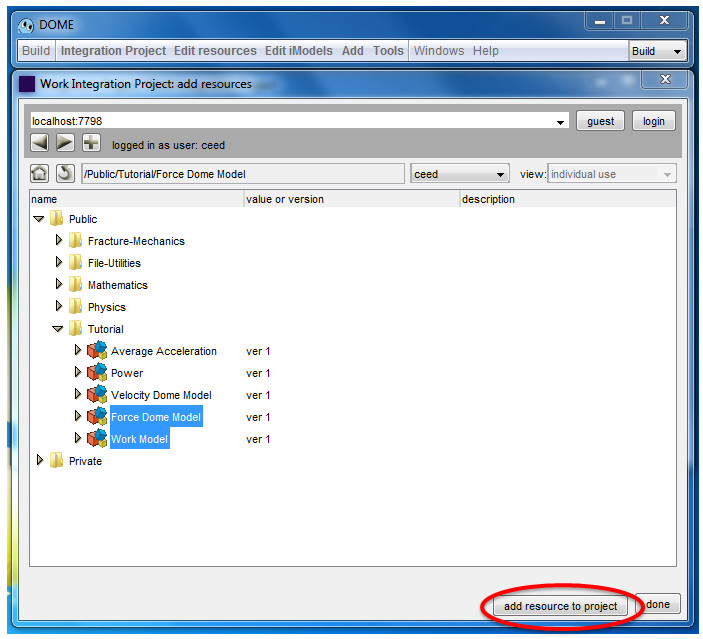
Figure 11
Once you have finished adding the resources you need, click done, Figure 12.
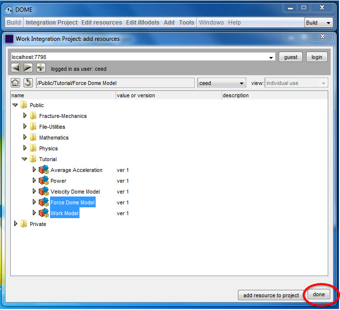
Figure 12
The add resource window will close and you will see that the resources were added to the Work Integration Project, Figure 13.
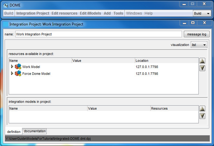
Figure 13
creating an integration model
Now you will create an integration model to add the resources' interfaces to. It is in this integration model that the inputs and outputs of each resource will be wired together. In the DOME client window, click Add -> Integration model, Figure 14.
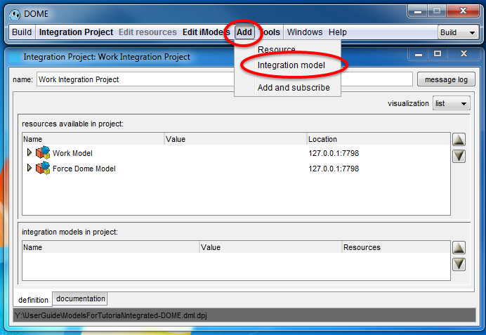
Figure 14
A new integration model with the default name "iModel" will appear in the "integration models in project:" list in the bottom half of the window, Figure 15.
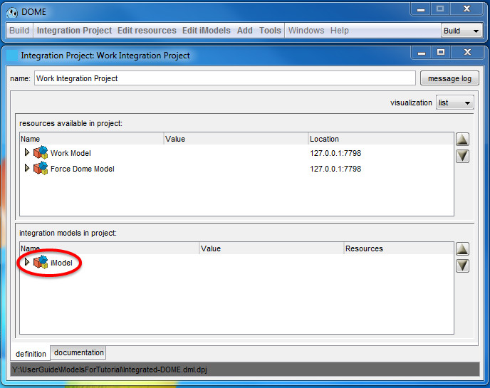
Figure 15
Open the newly created integration model by double-clicking on the cubes icon image next to "iModel". This will open a new window titled "Integration Model: iModel", Figure 16.
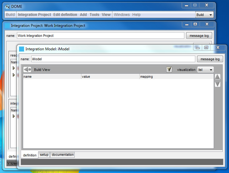
Figure 16
Change the name of the iModel to something else, in our case it is Work Integration Model, Figure 17.
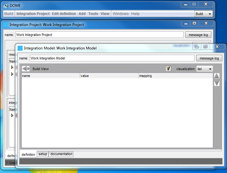
Figure 17
Add the interfaces of the resources to this integration model. In the DOME client window, choose Add -> Subscriptions, Figure 18.
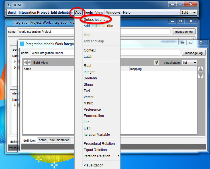
Figure 18
A window listing the resources will appear, Figure 18
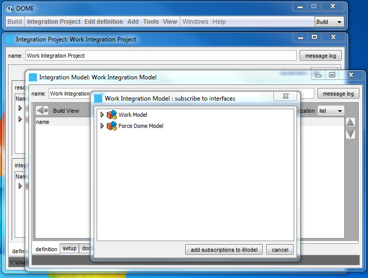
Figure 19
Expand each resource and select the interface to add to the integration model. In our case there is only one interface per model, but in general one model can have many interfaces. Click the add subscriptions to iModel button at the bottom, Figure 20.
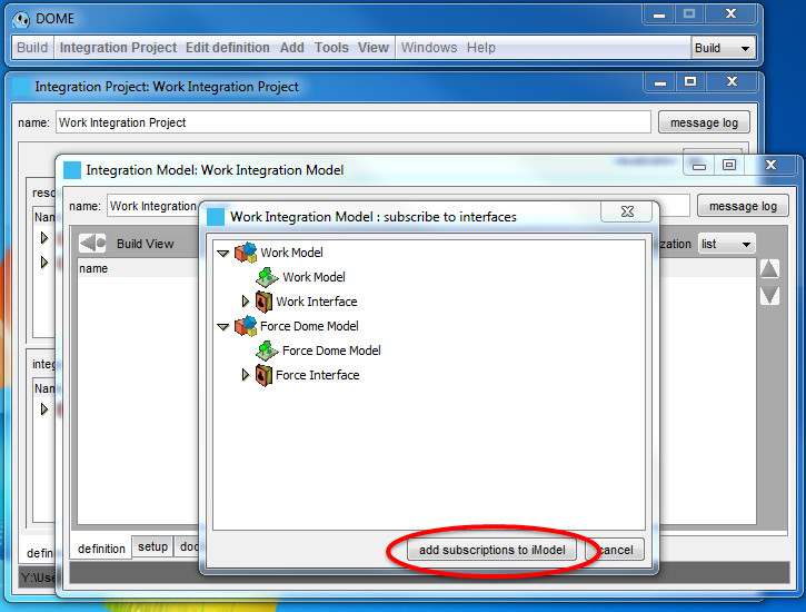
Figure 20
The interfaces chosen are now added to the Work Integration Model, Figure 21.
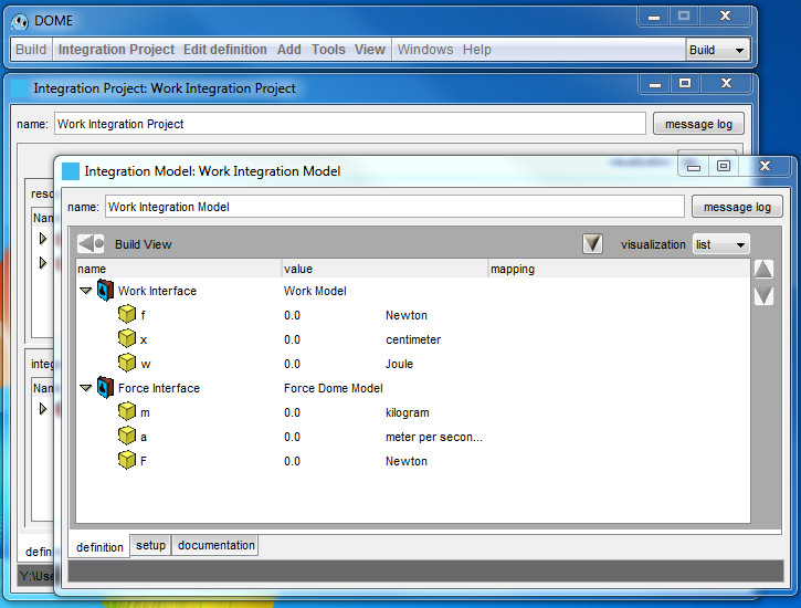
Figure 21
creating mapping between parameters
The Integration Model Window shows the list of input and output parameters for each resources interface. Notice the "mapping" column in the display. As inputs and outputs are wired to each other, the mapping column will reflect the parameter it is connected to (i.e. "mapped" to). To do this in general, select either the input parameter or output parameter (it doesn't matter which) by clicking on the yellow cube icon of the parameter, then go to the DOME client window menu Edit Definition -> Copy. Then, select the parameter to map to (again select the yellow cube), and in the DOME client window, do Add -> Map -> Last Selection. Since we copied the input parameter to the clipboard via the Copy step, it is the last selection and is now mapped to the currently selected parameter.
In this example we want to map the F (force) of the Force Interface to the f (force) of the Work interface so that when the force is computed with the Force model it will become an input of the Work model.
- Select the F parameter (select the yellow cube) of the "Force Interface"
- "Edit definition" -> Copy.
- Select f parameter of the "Work Interface"
- Add -> Map -> "last selection".
The "mapped" column should now show the parameters they are mapped to. f from the work Interface is mapped to F from the Force Interface Figure 22.
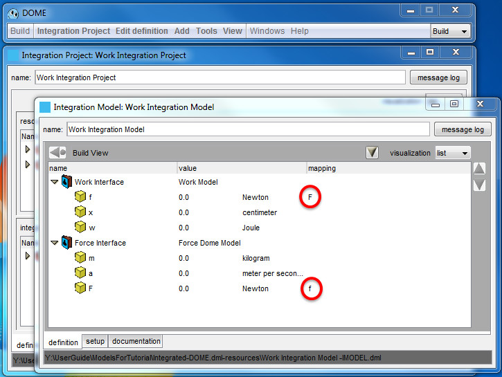
Figure 22
In this example only one parameter needs to be mapped. If you want to map more than one parameters repeat the above step.
defining project interfaces
Now we will define the interface of the integrated model. Click on Tools ->Project Interfaces, Figure 23.
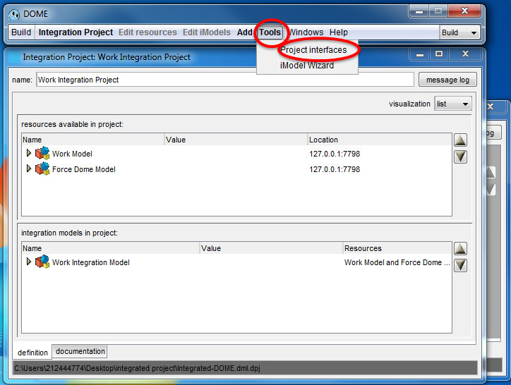
Figure 23
This will display an empty "Interfaces: Work Integration Project" window, Figure 24.
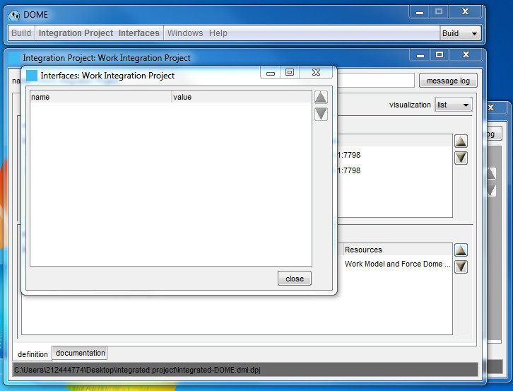
Figure 24
In the DOME client, click Interfaces -> New, Figure 25.
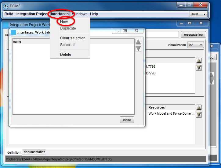 Figure 25
This will create a new interface with the default name "Project Interface" in the window, Figure 26.
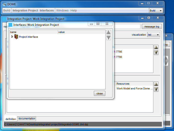
Figure 26
Double-click on the icon next to "Project Interface". This will display the Interface window. Rename the interface as appropriate, Work Integration Project Interface in our case, Figure 27.
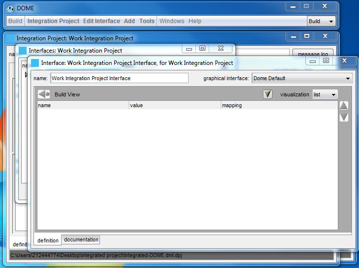
Figure 27
Put the integration model window in the foreground. In our case it is the "Integration Model: Work Integration model", The one that displays the yellow cube mapped interfaces, Figure 28.
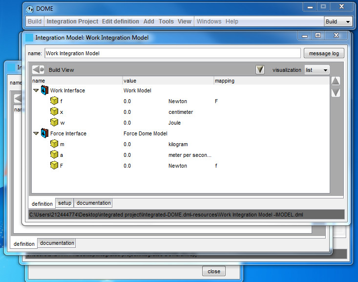
Figure 28
Select the parameters you want to expose in the integration project's interface, from the mapped interfaces window now visible, then in the DOME client, do "Edit Definition" -> Copy. In our case we want to add to the interface m and a from the Force model and x from the Work model, Figure 29.
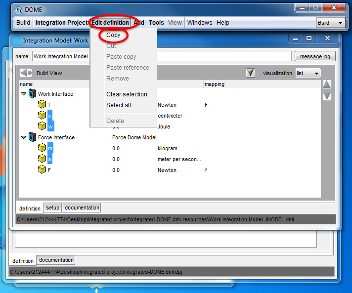
Figure 29
Click on the empty "Interface: Work Integration Project Interface" window that was slid off to the side, then in the DOME client, do Add -> Map -> "last selection". This will add the selected parameters to the integration project's interface as exposed parameters, Figure 30.
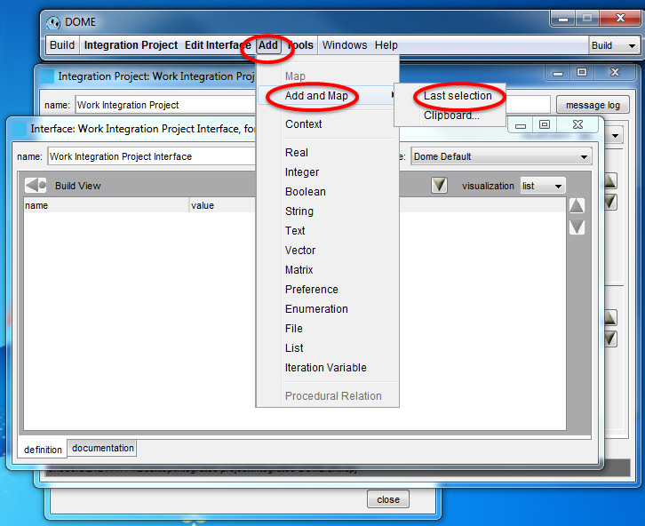
Figure 30
The parameters x, m, a and w are now added to the interface, Figure 31.
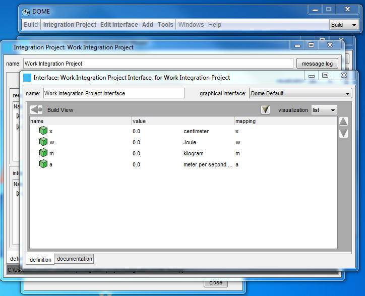
Figure 31
Save the integration project.
To deploy the integrated model follow the same procedure as you do for an individual model, but deploy the integrated project instead of a model.
To run the model follow the same procedure of an individual model.
Articles in this series:
DOME (Distributed Object-based Modeling Environment) - User Guide