Use Case For a Generative Robotic Fully Articulated Probe in DOME: Example using Solidworks
1: Abstract
This article is to facilitate the creation of design models in SOLIDWORKS® and DOME which can be further used to predict integrated product performance with the ultimate goal to make tradeoffs between many options. Ulrich and Eppinger[1] have analyzed product development as a process starting from market opportunity and ending in production, sale and delivery of a product. This applies very well in this use case, where a base case financial model of a product can be built easily using CAD tools like SOLIDWORKS®, and DOME Models. In this document we discuss a Robot that is designed in SOLIDWORKS® and can be fully automated using powerful macros. Most importantly non CAD professionals can view the assembled robot in free viewers like eDRAWINGS® from Dassault Systems which is available for Windows, Mac and Mobile devices.
2: Introduction
Snake Robot [2] can be used for several applications like search and rescue and inspection purposes. In this document we discuss a high level plan including the design, control and evaluation of a generative robotic fully articulated probe( aka snake robot). Figure 1 shows three parts designed in SOLIDWORKS® that can be mated to create one segment of a Robot. In this use case, the end customer can create a robot with several segments so that the snake robot can reach the part that needs to be inspected.
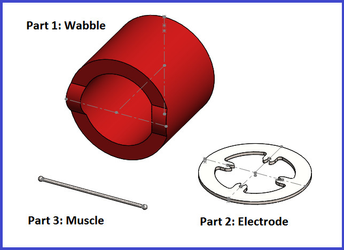
Figure 1: Parts of the Robot
Solidworks-Dome Plugin ( Note the plugin is part of DOME) lets users select/modify the dimensions of a part or assembly via DOME interface. This provides clients( users) to evaluate the part without having to have individual Solidworks license because the DOME server installs SOLIDWORKS® with a valid license. Typically one changes one or more dimensions of a part via the DOME user interface and gets as output volume, surface area, mass , angles and colors. However, in 2016 we have added additional capability to the Solidworks-Dome Plugin. We allow custom properties that can be passed from DOME user interface which is further used by SOLIDWORKS® in macros.
A SOLIDWORKS® macro is a shortcut to a task you perform repeatedly in SOLIDWORKS® 3D CAD software. It is a series of commands and actions that can be stored and run within SOLIDWORKS. Microsoft VBA , a toolset based on Microsoft Visual Basic , is embedded in the SOLIDWORKS® software.
In our design/architecture of the Solidworks-Dome Plugin we expect the macro embedded in the assembly file. In this use case, the Number of Segments is a custom property that can be set in DOME and SOLIDWORKS®creates the robot with the defined number of segments. The details of the macro will show how we can mate the parts, and come up with the final product.
Ulrich and Eppinger[1] discuss various types of prototypes as shown in Figure 2. They also show how it is not feasible in the Analytical-Comprehensive quadrant. However with tools like DOME and plugins and CAD tools we think this can be more feasible. An integrated product design simulation is feasible.
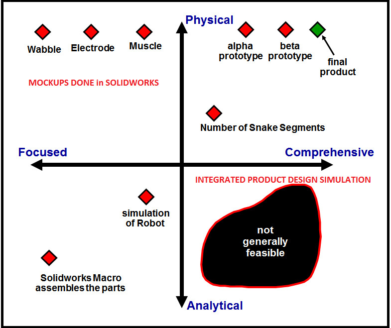
Figure 2: Types of prototypes by Ulrich and Eppinger
3: Use Case Actors
Figure 3 illustrates at a very broad level the tasks performed by DOME/DMC developer so that the actors like Product manager, Engineering Manager and Costing Engineer can benefit by this application. The Product Manager would have already identified the product after conducting market research, generating product requirements; determining specifications, production timetables, pricing, and time-integrated plans for product introduction. The Engineering Manager supervises and lead engineers, scientists and technicians who design machinery, plan and develop projects, This role will be able to decide how many of the Snake Segments one needs for the project, what kind of material (Steel , aluminium etc) to select, figure out if the robot can pass through the cavities etc. This team of engineers will be using the DOME Client interface. This then goes to the Costing Engineer who will estimate cost , perform some cost forecasting, investment appraisal and risk analysis. The Costing Engineer can also request other DOME models which can use the output from this use case and figure out the cost. [ Please refer to Building Integrated Models in DOME]. For example a DOME Model can use the Excel Plugin and give the Costing engineer the ultimate cost. We discuss each of the tasks shown in the left part of the figure which deals with the development of DOME client/server and development of the macro in SOLIDWORKS®
Figure 3: Actors in Use case
4: Designs Macro Embedded in Solidworks
We introduced the three parts that are designed by the SOLIDWORKS® designer (CAD) to create this Snake Robot. The dimensions for each part is designed so that the mating of the parts can be done. We could have exposed the dimensions as parameters that can be controlled from the DOME interface. But this will have to be designed carefully so that the mating succeeds in the macro. We did not do it in this use case, but this is possible.
This macro needs the number of segments that the Dome Client sets as a Custom property. Figure 4 shows the SOLIDWORKS® setup.
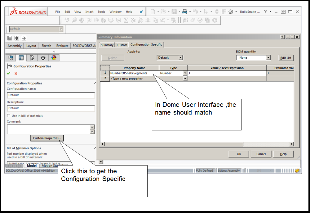
Figure 4: Configuration setup in Solidworks which uses custom properties
The macro is embedded in the Assembly (SLDASM) file. Figure 5 shows the SOLIDWORKS® interface. The name of the assembly file for this use case is
BuildSnake_ Assembly_Demo.SLDASM. The name of the macro is BuildSnake_ Assembly_Demo.swp.
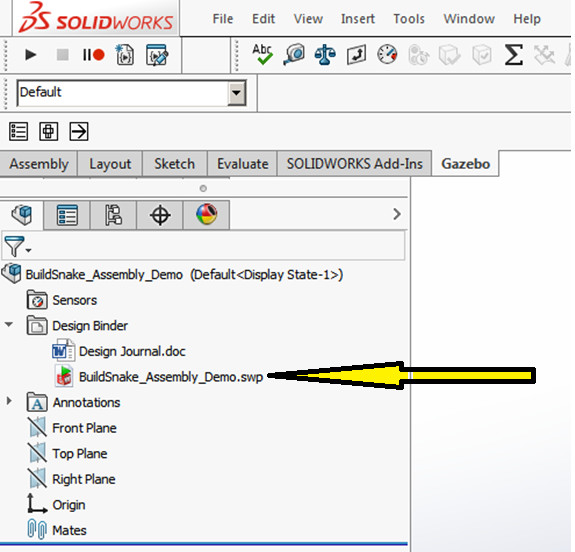
Figure 5: Macro is embedded in the Solidworks assembly file
The VBA code (Dome_Solidworks_Module.bas) of the macro has several functions and the table below explains each of them. Note that the assembly file (BuildSnake_ Assembly_Demo.SLDASM) is opened by DOME and the macro executes . The number of segments is set ( see Figure 3)
The VBA code will also show you that the module name is Dome_Solidworks_Module for the macro BuildSnake_assembly_demo.swp. This module name cannot be changed. The Solidworks-Dome plugin expects this module name so that the attached macro can be run automatically.
| Function or Sub Name in macro | Description |
|---|---|
| GetNumOfSegmentsFromConfig | Note that DOME client sets this number. This macro reads the number of Snake Segments. If N=3, the end robot will show 6 segments of the snake. We have 3 Even number segments and 3 Odd number segments |
| InsertFirstWabble | Wabble is one of three three parts named as Wabble.SLDPRT. This part document is opened and inserted in BuildSnake_ Assembly_Demo.SLDASM |
| InsertFirstElectrode | Electrode is one of the three parts named as Electrode.SLDPRT. This part document is opened and inserted in BuildSnake_ Assembly_Demo.SLDASM |
| InsertSecondWabble | Insert another wabble. Note some mating is done before this happens |
| Mate_ElectrodeConstructionLine_RightPlane | Two points in the Electrode are mated |
| Mate_First_Coincident_Electrode_Wabble | Electrode backface and Wabble frontface are mated |
| Mate_First_ElectrodeAndWabbleCenter | Electrode and Wabble center are mated |
| Mate_Muscles_EvenNumberedSegments | Muscles mated with even number segments |
| Mate_Muscles_OddNumberedSegments | Muscles mated with odd number segments |
| Mate_NewWabble_PrevElectrode | This can happen only after the second wabble is inserted |
| Mate_SecondElectrode_SecondWabble | This adds the second electrode and mate to the second wabble in the pair |
| Mate_SecondWabble_PrevElectrode | Selects and aligns the new wabble to the previous electrode |
| SaveAsNewAssembly | After all the segments are added, we save the assembly file with a suffix of _Rebuilt. In this case it will be BuildSnake_ Assembly_Demo_Rebuilt.SLDASM. This can be used for debugging purposes, because this will be at the DOME server Auxfiles ( for the model) |
5: Create DOME Model
Basics of Creating a DOME model is not covered here. We are highlighting how the inputs and outputs are defined for this application.
Step 1 : Name the Model and start with SLDASM FILE
Figure 6 shows how we start with Create, Solidworks Model, and we have the name as Snake Robot
We have started by adding SLDASM file to a context named as Inputs, which is the Assembly file in Solidworks. Note that this file has the embedded macro file shown in Figure 5 above.
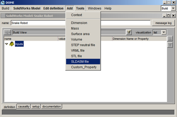
Figure 6: DOME Model
Step 2 : Add all other parameters
Figure 7 shows all the parameters added to the model. The eDrawing file and the Snake Robot Assembly file do get updated by the macro and is available for the Web interface to handle it as appropriate.
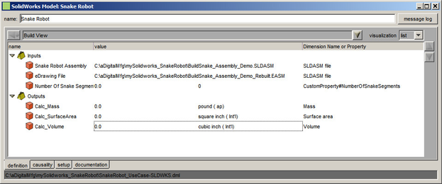
Figure 7: Definition of Dome Model
Summary of the inputs and outputs defined in Figure 7
| Parameter name | Notes |
|---|---|
| Snake Robot Assembly | This file is created by using SOLIDWORKS® . See Figure 4. This is empty with no parts added. All it has is the Configuration details needed by the Macro to run. The name of the macro is embedded in this file. |
| eDrawing File | The eDrawing file, as input, is a blank file created using SOLIDWORKS® . The macro expects the value ( name ) of the file to be same as the Assembly file with a suffix of Rebuilt. eg Our Assembly file is named as BuildSnakeAssembly_Demo.SLDASM, so we expect the eDrawing File to be named as BuildSnakeAssembly_Demo_Rebuilt.EASM |
| Number of Snake Segments | CustomProperty#NumberOfSnakeSegments is a Custom_Property. This MUST have the prefix CustomProperty#. The NumberOfSnakeSegments that follows the prefix MUST MATCH what is defined in the SLDASM file. See Figure 4 above. |
| Calc_Mass | SOLIDWORKS® calculates the Mass of the assembled Robot. The material selection is already made in the part as 1023 Carbon Steel. The Assembly file has units selected as pound, so the DOME user interface must select pound. |
| Calc_SurfaceArea | SOLIDWORKS® calculates the Surface Area of the assembled Robot. The Assembly file has units selected as square inch, so the DOME user interface must select square inch. |
| Calc_Volume | SOLIDWORKS® calculates the Volume of the assembled Robot. The Assembly file has units selected as cubic inch, so the DOME user interface must select cubic inch. |
Step 3 : Define the causality
SOLIDWORKS® can evaluate Mass, Volume, surface area. All it needs is the Assemebly file and the number of snake segments. The eDrawing file is added in this causality so that the updated eDrawing file can be used by the Web interface.
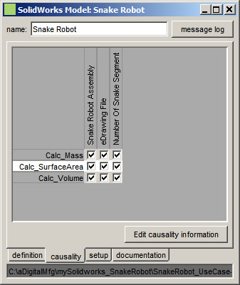
Figure 8: Causality of Dome Model
Step 4 : Define the setup
All the part files (SLDPRT) are needed by the macro. Our Solidworks-Dome plugin will start with the main model file, so make sure the Snake Robot Assembly file is defined here as the main model file. All the parts are designed for Material 1023 Carbon Steel. This information can be used in Costing.
This use case will work for Solidworks 2016 version.
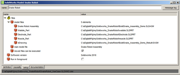
Figure 9: Setup of Dome Model
Step 5 : Running the Model
The Dome Model defined as a default interface for this model is shown in Figure 10 . The Red background parameters are Output parameters from the model. In this example we set the number of snake segments to 5 before we press submit. Note that the macro will expect the eDrawing file to be same as the Assembly file with suffix of _Rebuilt.
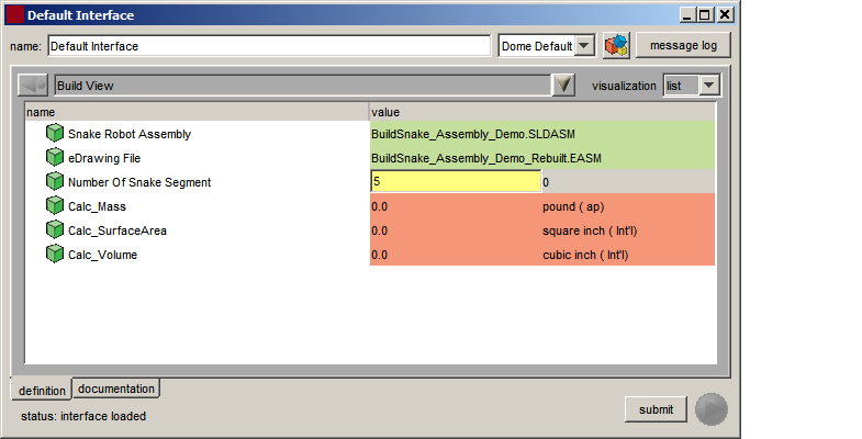
Figure 10: Input params when DOME model is in Run Mode
Step 6 : Results returned from Solidworks
If the model runs successfully all the output parameters are updated here as shown in Figure 11. These output parameters can become input to another DOME model, which we discussed above if the costing engineer wants to derive cost.
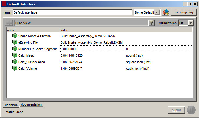
Figure 11: Output params updated after DOME model is in Run
Step 7 : Fully assembled Snake Robot
Figure 12 shows the fully assembled Robot with the defined number of segments. However, this will be seen in SOLIDWORKS®at the server, and will be lost after the DOME interface is closed. The updated Assembly file and the eDrawing file is available before the DOME interface is closed.
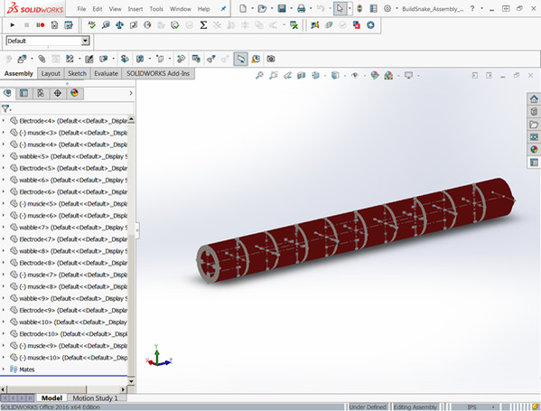
Figure 12: Fully assembled Snake Robot
Step 8 : Robot can bend at any segment
Figure 13 shows how the advanced mating done enables the robot to bend at the segment. When we defined 5 segments, the macro creates the robot with twice as many segments defines in the DOME interface so that the bend can happen.
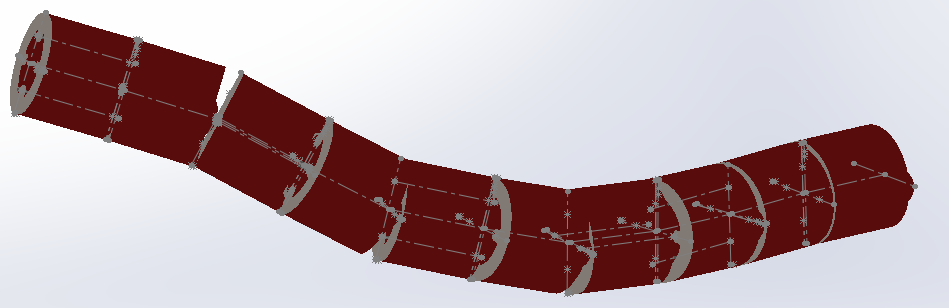
Figure 13: Fully assembled Snake Robot showing bends
6: Develop gaps that are not in DOME/DMC
MIT had developed Solidworks-Dome Plugins versions 2000, 2001, 2002, 2003 and 2004. However SOLIDWORKS® does not support the Solidworks-Dome Plugins(2001- 2004). We earlier versions (2004 -2004) of SOLIDWORKS® . So we have created Solidworks-Dome Plugin version 2016, that will work with SOLIDWORKS® 2016. The new Solidworks-Dome plugin is SolidWorksPluginNew64.dll. This should be in the dlls directory.
Also Solidworks-Dome Plugins(2001- 2004) did not support Custom_Property, so we have added that in this version. Without the Custom_Property we cannot support Macros embedded in Assembly files.
7: Visualization in Dome Client/Web Interface
One of the advantages of using DOME-Solidworks plugin is that every actor of this use case application does not need to have SOLIDWORKS® license. But most actors of this use case application can visualize the fully assembled Robot. The macro designed/developed here saves the fully assembled Robot as a EASM file. More specifically we have the BuildSnake_Assembly_Demo_Rebuilt.EASM saved by the macro. This EASM file can be viewed by eDRAWINGS® from Dassault Systems, which is free and can be downloaded from the web. Figure 14 shows the EASM file in the eDRAWINGS viewer.
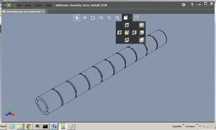
Figure 14 eDRAWINGS viewer showing the Snake Robot
8: References
1] Karl T. Ulrich and Steven D. Eppinger, Product Design and Development, Irwin McGraw-Hill
2] From Wikipedia https://en.wikipedia.org/wiki/Snakebot