Building DOME Models
Starting a new model and building mathematical relations
You will learn how to:
- Create a new model;
- Add parameters to the relation;
- Change parameter names and units;
- Add a mathematical relation;
- Edit the causality;
- Test the model.
Introduction
We will build a simple DOME model to compute velocity given initial velocity, acceleration, and time using the equation v = v0 + a*t.
Start the DOME Client: :
- Launch the script:
- Windows: Open command prompt, navigate to directory with DOMEClient.bat and run DOMEClient.bat. Note: Must do this from Command Prompt, can't just click .bat file to open.
- Mac: DOMEClient.sh (permissions/path might be wrong, if so try: $ sh DomeClient.sh)
- Linux: $ sudo sh DomeClient.sh
- Click Run. OK to ignore errors in Command Prompt window.
- When the DOME3 Copyright pop up opens, accept the Terms and Conditions.
- Launch the script:
At this point, the DOME Client will open. Do not close the Terminal, Command Prompt, or PowerShell window.
The DOME Client is the thin toolbar shown in Figure 1. At the right of the bar you see Build to indicate the mode. The four modes are Build, Deploy, Run, and Server. The rest of the tool bar changes automatically to reflect the mode.
The following client will appear when you start DOME (Figure 2). We call it the DOME Window. 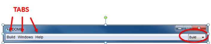
Figure 2 DOME Window
As mentioned before, the DOME toolbar tabs will change according to the active mode. There are four options.
Click on the mode dropdown menu at the top right and the four modes will appear (Figure 3).
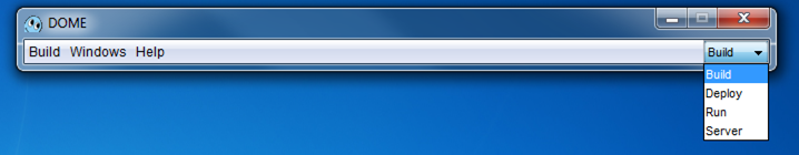
Figure 3
Build is used to build a model, enter variables, and build the interface.
Deploy is used to deploy a model interface to the server so that other users can access it.
Run is used to run a model interface found on the server.
Server is used to manage the server.
Create a new model
To build a new model, you must be in build mode.
Click on Build > New Model on the left side (Figure 4).
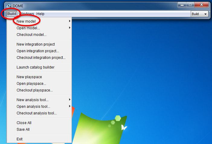
Figure 4
You can choose from many different types of models. For this example, click on Dome Model (Figure 5). A Dome Model allows you to execute a Python script. In this tutorial we will build a Dome Model.
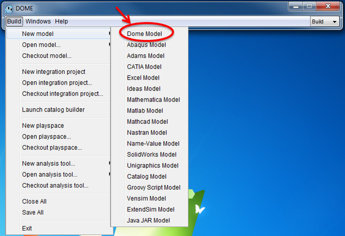
Figure 5
The DOME window will change to show more options and a model window appears with the default name Dome Model (Figure 6).
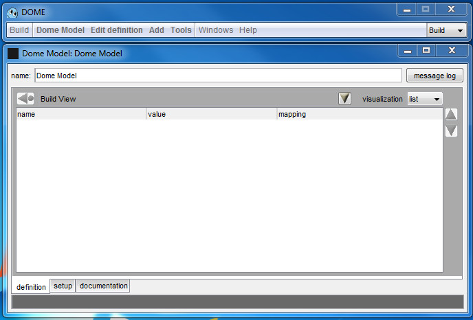
Figure 6. Model Window
While the DOME window is a fixed menu bar, the Model Window size can be changed.
Change the name to the model name you want, we chose “Velocity Dome Model”. Hit Enter/Return to update the name (Figure 7). The name field will change from yellow to white to show the change has been accepted. Save the model to save the new name.
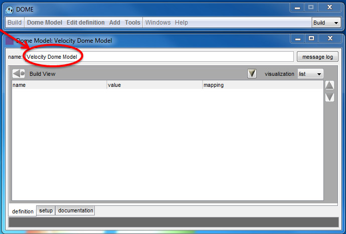
Figure 7
Now we will add a relation to the model. Click Add in the DOME window (Figure 8).
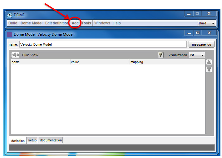
Figure 8
Click on Procedural Relation (Figure 9).
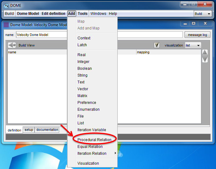
Figure 9
A Procedural Relation will appear inside the model window (Figure 10).
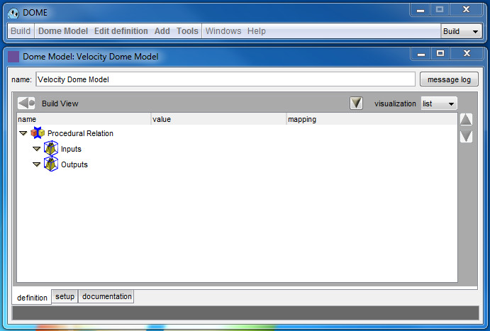
Figure 10
Double click on the name and change the name of the relation to something that reflects the model you are building. We chose “Velocity Relation” (Figure 11). The name will be updated when you press enter or click elsewhere in the window, again changing color from yellow to white. Save the model to save the new name.
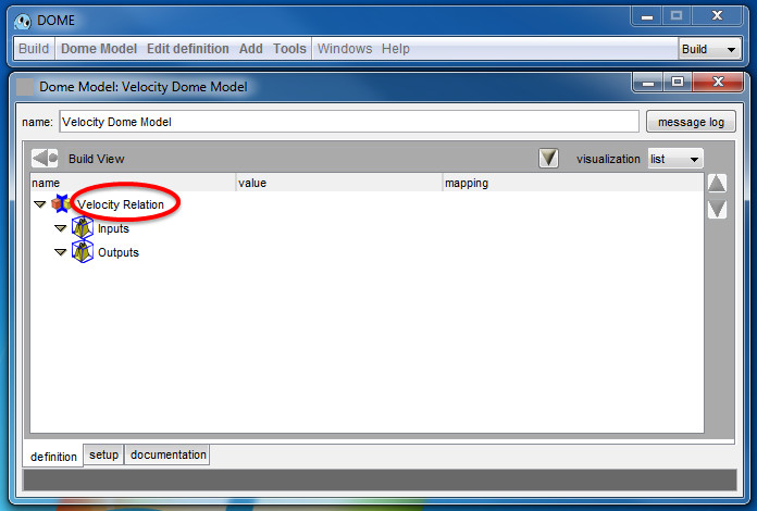
Figure 11
Note that changing names will update them but not save them. You can save the model at any time. From the DOME window, click on DOME Model > Save (Figure 12), and follow the instructions. A .dml file and a folder will be created.
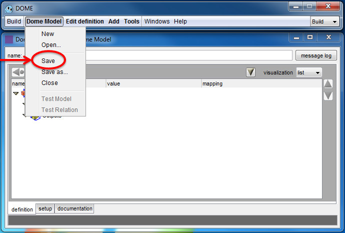
Figure 12
Add parameters to the relation
From the model window add four Real parameters (data with the “real” type). These will represent velocity, initial velocity, acceleration and time in the model.
To do this, click on the yellow triangle to the left of "Velocity Relation" to expand the relation (if you just created it, it's already expanded), and then expand the Inputs and Outputs folders as well (they will be empty). Your window should look like Figure 13 when all are expanded. From the DOME window choose Add > Real four times to add four Reals to the relation (Figure 13). The parameters will be added under Inputs. In a later step you will tell the model which are outputs by defining the relation’s causality; right now, with no causality defined, the model considers them all to be inputs.
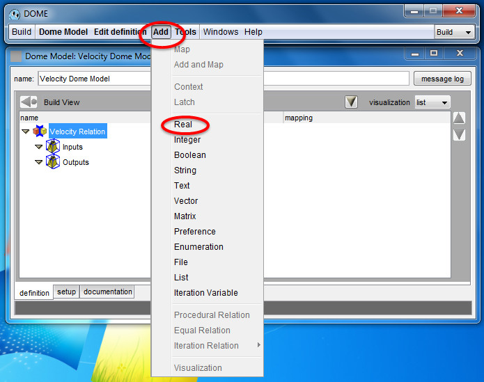
Figure 13
The model with the four Real parameters is shown in Figure 14.
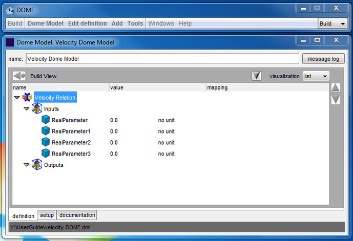
Figure 14
Change parameter names and units
Double click on the name of the parameters to change them to something meaningful for the model you are building. In this case use v for velocity, v0 for initial velocity, a for acceleration and t for time.
Click on “no unit” and then “change unit” to choose the correct units for each parameter. A unit chooser window opens (Figure 15).
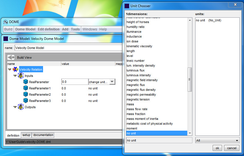
Figure 15
Choose a dimension in the left column and then a unit in the right column (Figure 16). For more information on how to use the unit chooser window see the special topic section on Units. For this example, select “meter per second” for the velocities, “second” for the time, and “meter per second square” for acceleration. Note the "All" on the bottom right. It is used to switch from all units to just metric units.
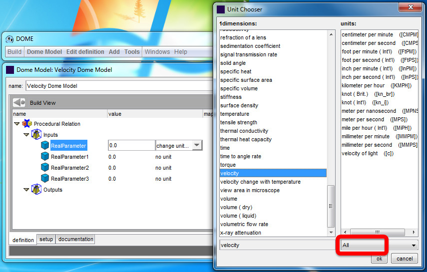
Figure 16
You can use units from different standards in one model as long as they have the same base dimensions (such as choosing “meter per second” and “foot per minute” for two velocities); DOME will convert internally when the model is run. Once the Units are chosen they are updated (Figure 17). Remember to save frequently.
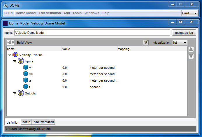
Figure 17
Add a mathematical relation
Double click on the red and yellow cube icon to the left of “Velocity Relation” that represents your procedural relation ( ) (Figure 18).
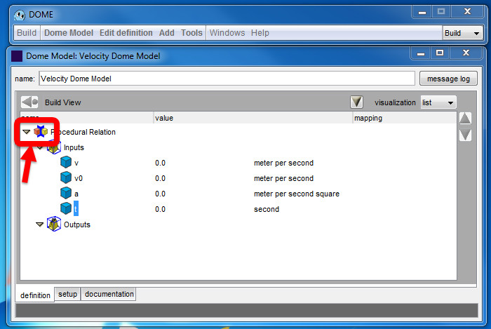
Figure 18
The relation icon will open () and a relation window will appear (Figure 19).
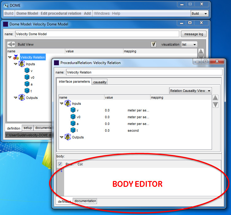
Figure 19
In the body editor write
v = v0 + a*t
as shown in Figure 20. The variables will turn blue to indicate that a matching input or output parameter exists.
The body editor follows Python
syntax, and relations are executed using Jython 2.5.4. For more detail, see the special topic section on Relation Body Editor, or reference the syntax in the Python documentation at https://docs.python.org/2/library/index.html.
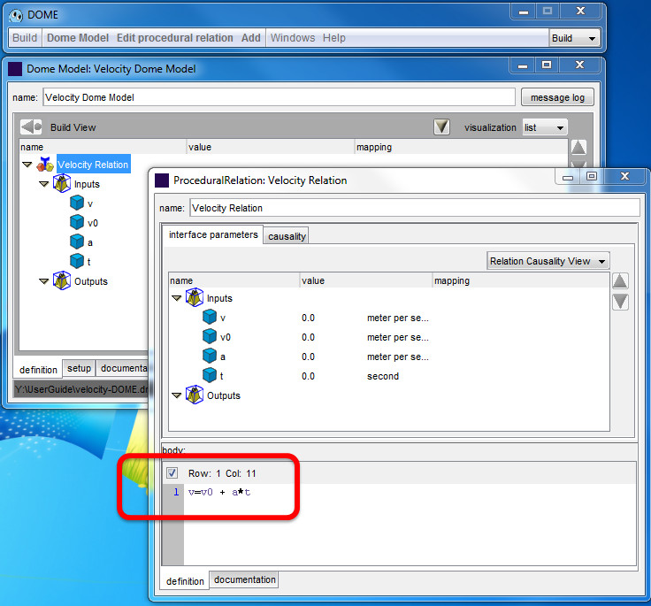
Figure 20
Edit the causality
Click on the causality tab inside the relation window (Figure 21).
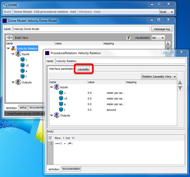
Figure 21
The view will switch to show the causality (Figure 22).
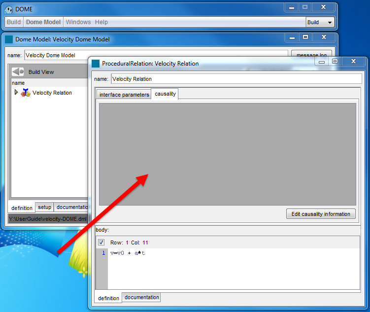
Figure 22
Click “Edit causality information” at the bottom right (Figure 23).
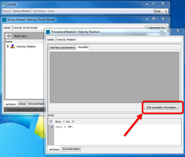
Figure 23
The Edit Causality Information window will open (Figure 24).
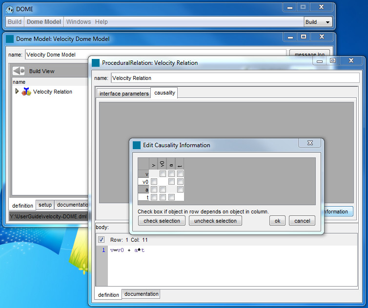
Figure 24
In the Edit Causality Window, check boxes where the parameter listed in the row is dependent on the parameter in the column.
In this case, v depends on v0, a and t, so check only the three squares in the first row (Figure 25).
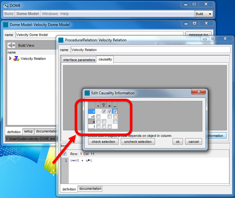
Figure 25
Click ok to accept (Figure 26).
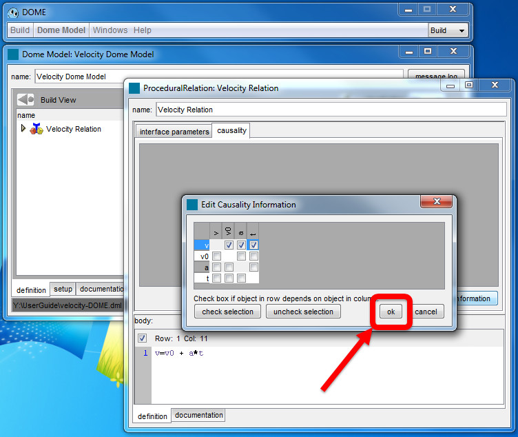
Figure 26
The causality Information Window closes, and the selected causality relations are shown in the relation window (Figure 27).
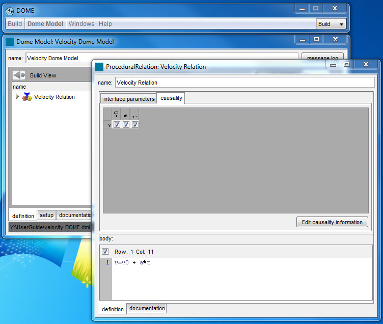
Figure 27
The causality is how you define your parameters to DOME. Based on your causality matrix, DOME will determine which parameters are the inputs and which are the outputs of your system.
Close the Causality Information Window clicking on the X. The velocity relation will show that v0, a and t are input parameters and v has moved to the Outputs folder (Figure 28).
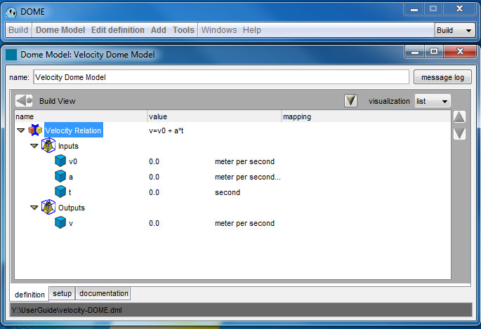
Figure 28
Test the model
If you have closed the Velocity Relation window, reopen it by double-clicking on the icon left of Velocity Relation in the Model window.
Go to the interface parameters tab in the relation window (Figure 29). You can move the divider bar up and down to increase the viewing size.
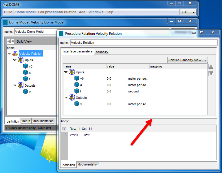
Figure 29
Change the values of the inputs in the velocity relation window. This example set v0=1, a=2, and t=3 (Figure 30). To do this click on the value (default 0.0) and enter a new number.
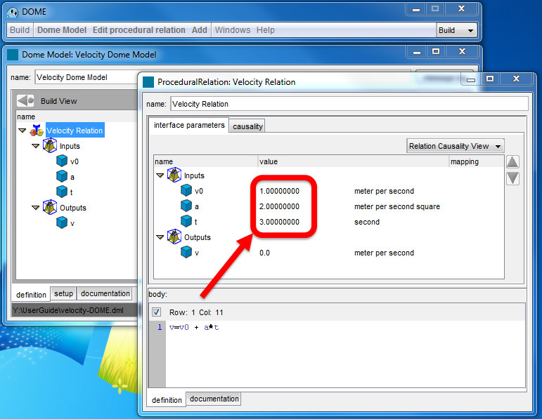
Figure 30
In the DOME Window, click Edit procedural relation> Test (Figure 31).
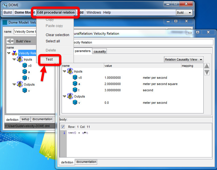
Figure 31
If the model is set up properly, the model will execute the Python script with the variables equal to the value column. The value of the output parameter(s) will then display the values returned by the script. If you used the values suggested earlier, the model will return v=7 (Figure 32). Testing the model also confirms that you have chosen units with the correct dimensions; if not, the model will give a unit error.
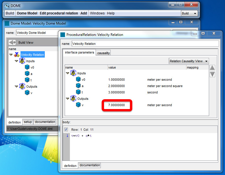
Figure 32
You may wish to close the procedural relation window before continuing.
Building interfaces for the model
Interfaces are the exposed views of a model made available through the server to users in Run mode. You will learn how to:
- Create a new interface;
- Add context items to organize the interface;
- Add parameters to the interface.
Create a new interface
First, close the velocity relation window and click somewhere in the velocity model window to bring it into the foreground. The menu options in the DOME window will change.
Click on Tools (Figure 33).
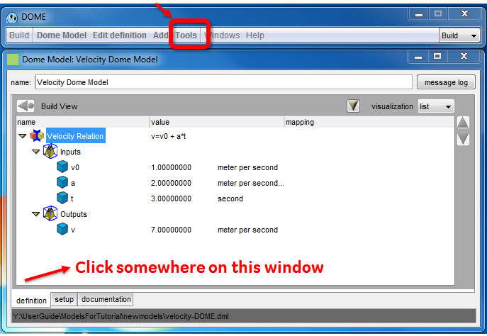
Figure 33
Choose Interfaces (Figure 34).
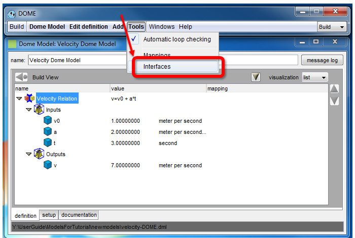
Figure 34
The Interfaces window will appear. It has been pre-populated with a Default interface (Figure 35).
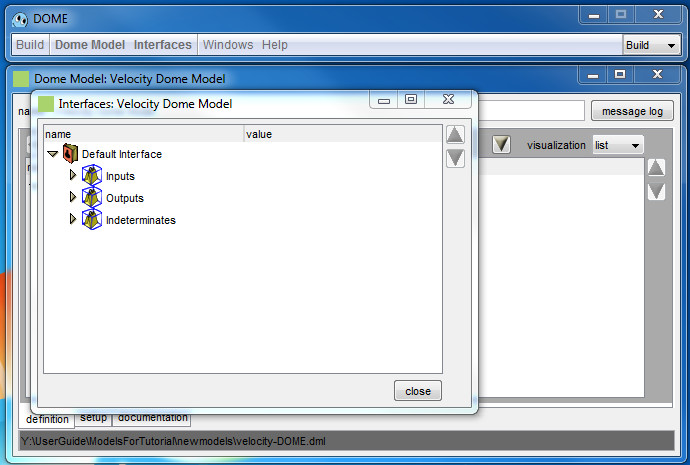
Figure 35
From the DOME window click Interfaces > New (Figure 36).
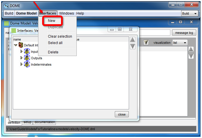
Figure 36
A new DOME Model Interface appears (Figure 37).
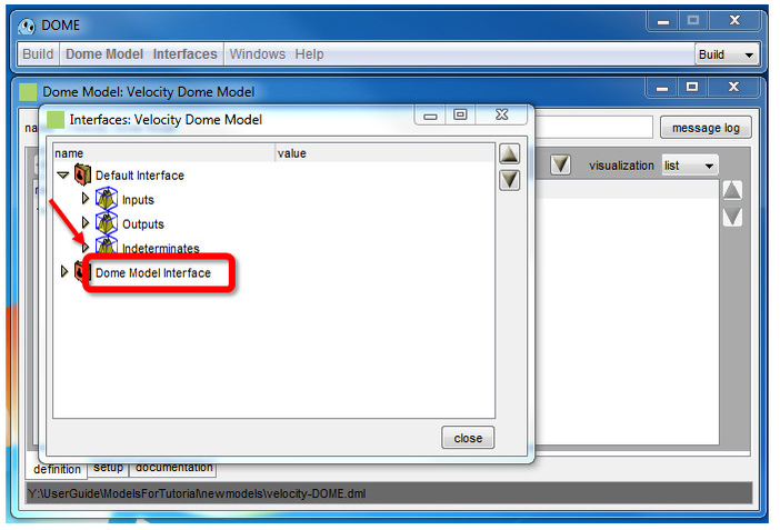
Figure 37. Interface Window
Double click on the name to change it to something meaningful, such as Velocity Model Interface (Figure 38).
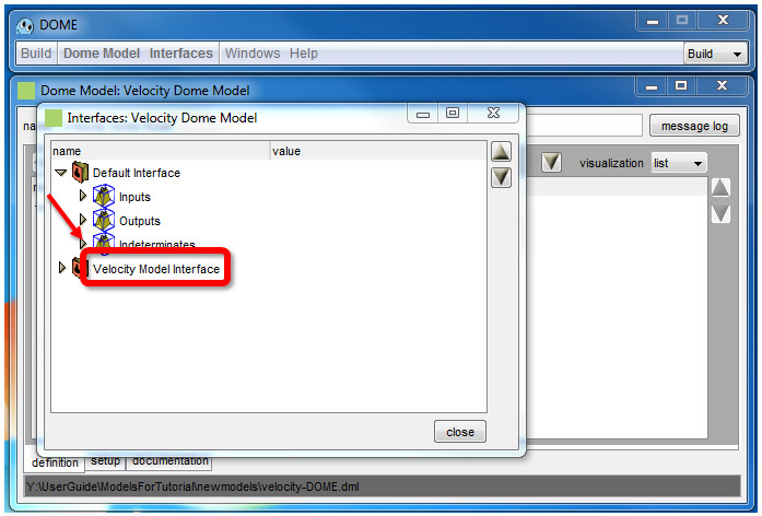
Figure 38
Add context items to organize the interface
Click to the arrow next to the name (  ) to expand the interface (Figure 39).
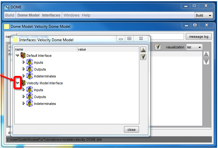
Figure 39
Double click the book icon ( ) next to the name of the interface (Figure 40).
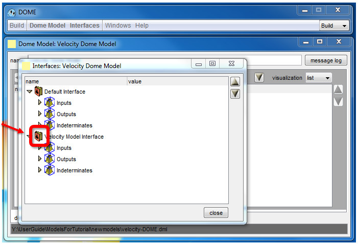
Figure 40
The velocity model interface window appears (Figure 41).
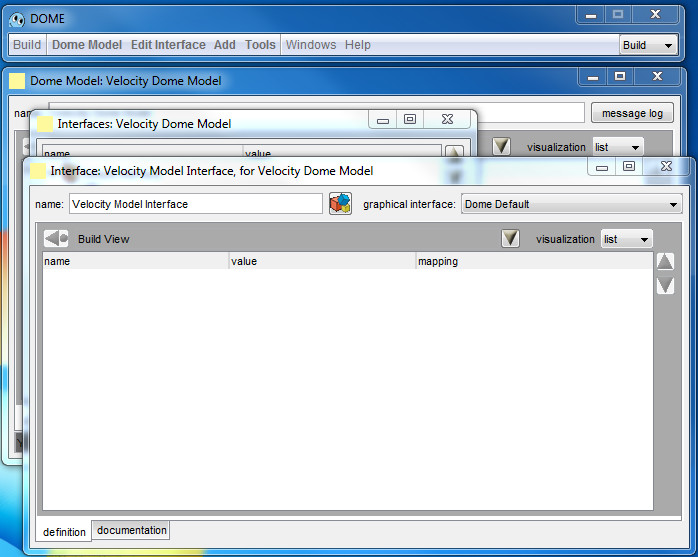
Figure 41
Click Add > Context to add a context item to the interface (Figure 42). A context organizes your interfaces, analogous to a folder in a file system.
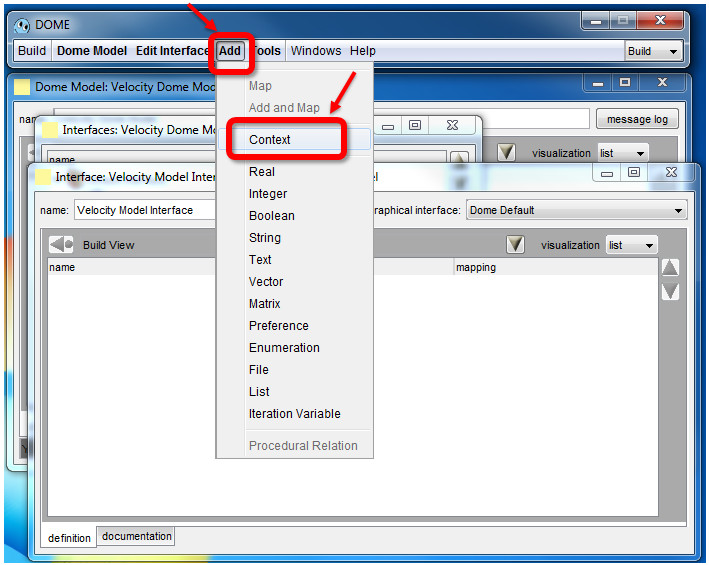
Figure 42
A new context item appears in the interface window (Figure 43).
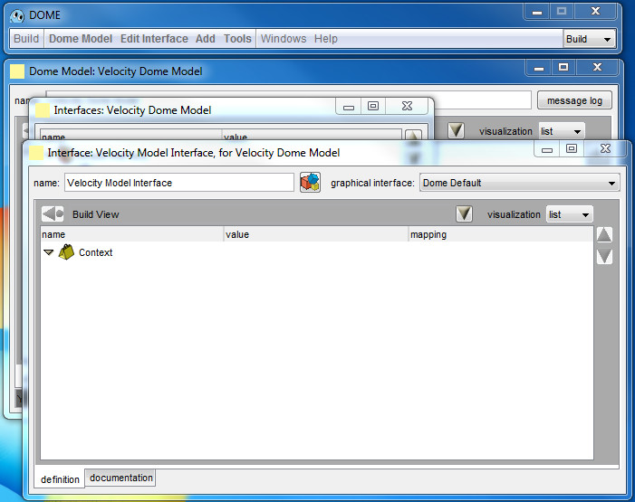
Figure 43
Double click on the context item to change its name to Input Dimensions (Figure 44).
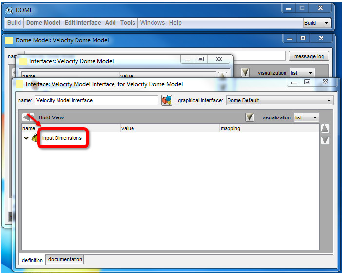
Figure 44
Collapse the Input Dimensions item (the triangle icon should point right), and add a second context item named Output Dimensions. Collapsing the first ensures that the new context won't be added inside it instead of at the highest level. Click Add > Context (Figure 39) and a second context item will appear (Figure 45).
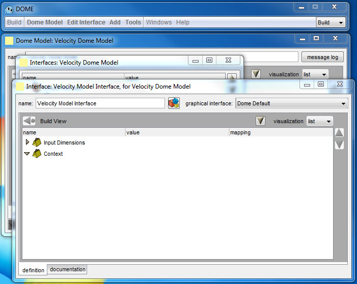
Figure 45
Double click on the name to rename the second item Output Dimensions (Figure 46).

Figure 46
Add parameters to the interface
Next, the interface needs to be linked to the model parameters. With the model window in the foreground, select the three input parameters, holding Ctrl to multi-select (Figure 47).
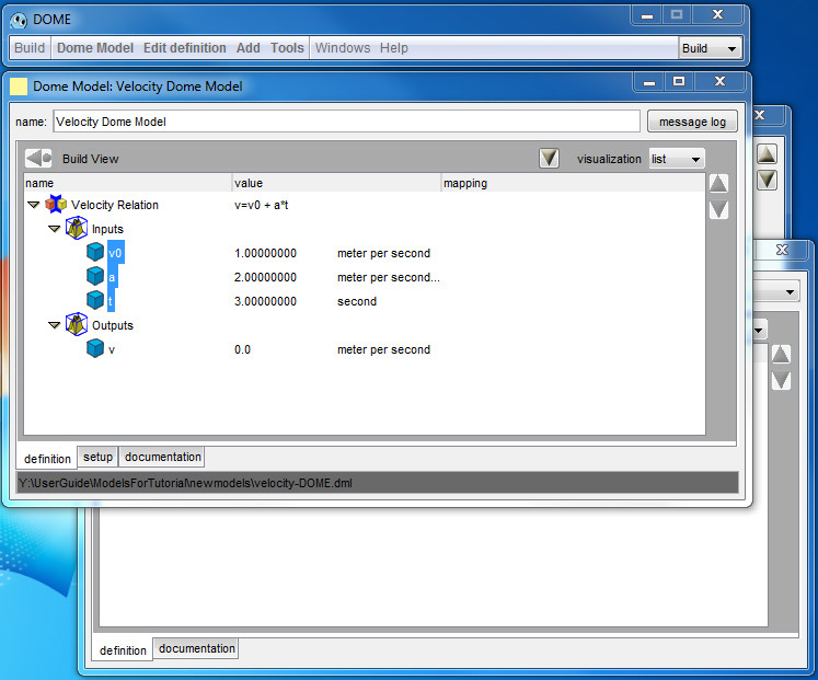
Figure 47
In the DOME window select Edit Definition > Copy (Figure 48).
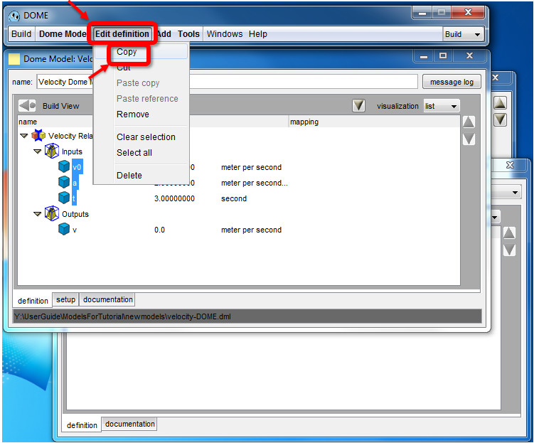
Figure 48
Bring the interface window to the foreground (Figure 49).
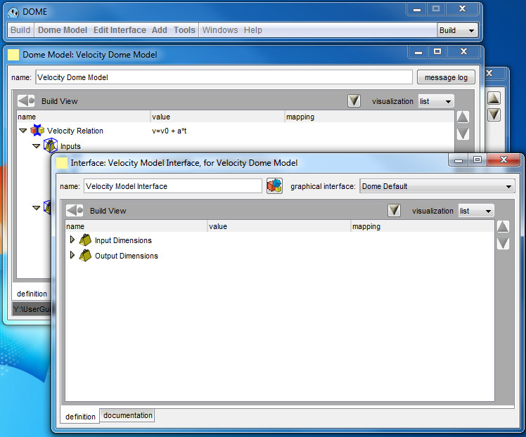
Figure 49
Click the yellow arrow to expand Input Dimensions, and then select the name Input Dimensions (Figure 50).
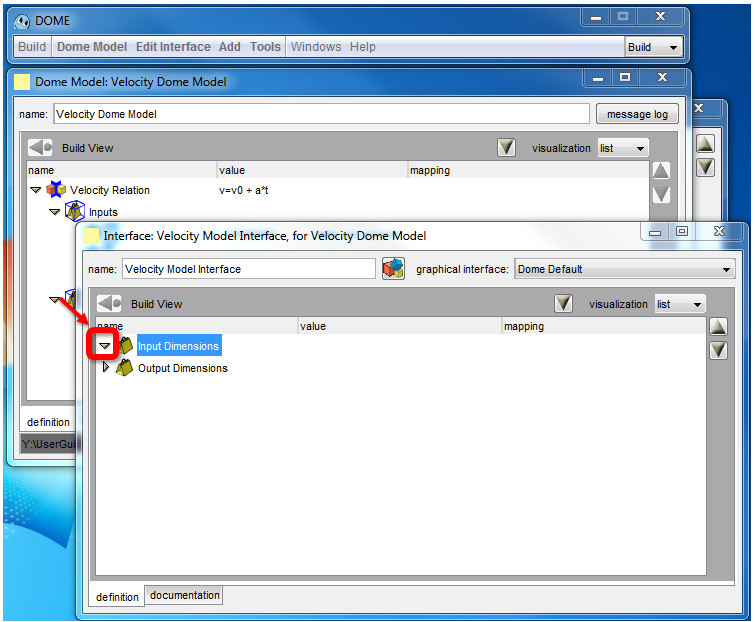
Figure 50
From the DOME window click Add > Add and Map > Last selection (Figure 51), which will add the parameters to the Input Dimensions context item (Figure 52).
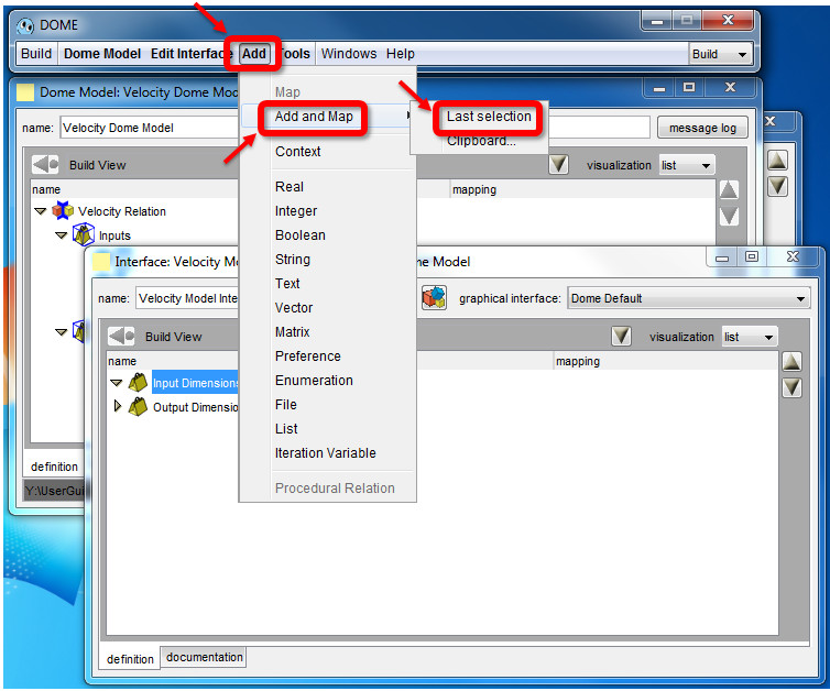
Figure 51
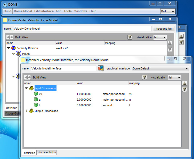
Figure 52
Repeat these steps for the output parameter. With the model window in the foreground select the output parameter, v (Figure 53).
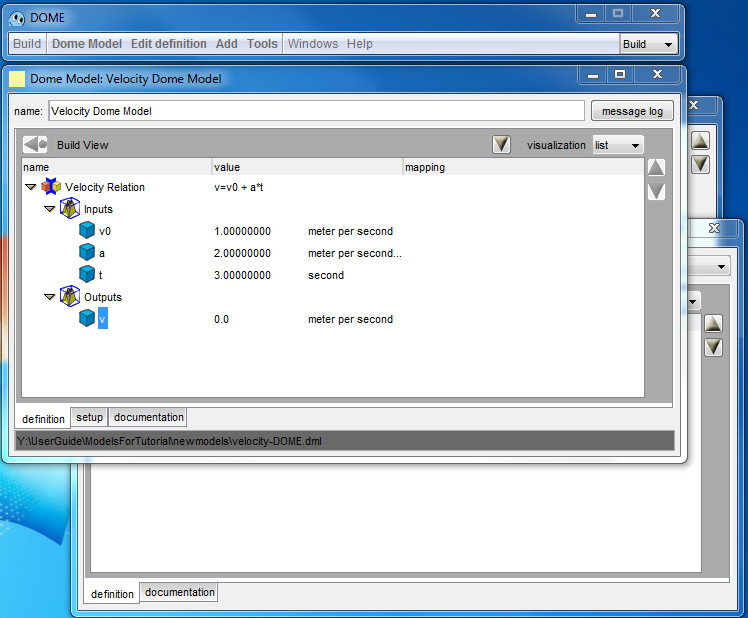
Figure 53
In the DOME window select Edit Definition > Copy (Figure 48). Bring the interface window in the foreground (Figure 49). Expand the Output Dimensions context item (Figure 54). And click on Output Dimensions

Figure 54
From the DOME window Click Add > Add and Map > Last selection (Figure 51) to add the parameter.
Click Dome Model > Save to save the model. The interface window may be closed.
At this point you have built a model and you have created an interface for it.
If you would like to test your model, please continue to Deploying to a DOME Server.